This is article-6 of how to define Synthesis timing constraint
A Multi-Cycle Path (MCP) is a flop-to-flop path, where the combinational logic delay in between the flops is permissible to take more than one clock cycle. Sometimes timing paths with large delays are designed such that they are permitted multiple cycles to propagate from source to destination. Unlike false paths, multicycle paths are valid and must be analyzed, but against more than one clock period.
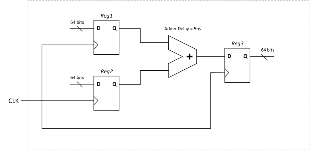
Consider an example as shown in Figure 1, where we have only one clock (of 2ns period) in our design and we are performing a 64-bit addition of two buses. The input buses to the adder, as well as the output bus from the adder are registered. The maximum delay of the adder is estimated to be around 5ns, and the period of the register clock is 2ns. Since the adder delay in more than time period of the clock, it is not possible to close the timing within one clock cycle.

For the circuit to operate correctly, a multi-cycle design approach was implemented. All the registers have a commonly connected enable bit, which is being controlled by a 3-bit shift register, which is preloaded with 001 and has a feedback loop from output to the input; this causes the enable signal to go high every 3 cycles.
If we simply apply a “create_clock -period 2 [get_ports CLK]” constraint, the synthesis tool will not analyze the enable control logic to understand that the adder has 3 cycles for setup check timing closure (as the tool doesn’t perform dynamic logic simulation). Therefore, it will try to optimize the adder logic to close setup time within 1 clock cycle, which is not possible (and unnecessary).
Therefore, we need to add multi cycle paths between the input registers and the output register. This is done by the set_multicycle_path command and by specifying a setup value of 3 (corresponding to 3 cycles), which is then applied on the paths which start at Reg1 & Reg2 and end at Reg3, as shown below –
set_multicycle_path -setup 3 -from {Reg1[*] Reg2[*]} -to Reg3[*]
Note: The [*] is added to consider all the bits (64 bits) of the registers.
By default (without any MCP constraint), setup checks are measured from the source clock edge to the destination’s next clock edge and hold checks are measured from the source clock edge to the destination’s same clock edge. In other words, we can also say hold timing analysis is performed in the same clock period where setup timing is performed.
Let’s say that a multi cycle path setup of N was applied, if no explicit hold multi cycle path is set, the default hold check will be performed at (N-1)th edge of destination clock. In order to meet this hold requirement, additional buffers will be added by the synthesis tool, which un-necessarily increases area, power etc. Typically, we only want to move the setup to the Nth edge of the destination clock and the hold check needs to be at the 0th edge of destination clock. In order to do this, we need to specify both the setup and hold multi cycle path constraint.
In the example we discussed, we have moved the setup capturing clock edge to the 3rd cycle (at 6ns), therefore the hold timing analysis is done by the synthesis tool at 4ns, which is within the same cycle as setup capturing edge. But this would mean the fastest path through this 64 bits adder under the fastest operating condition has to be slower than (4ns + hold time of Reg1 or Reg2), which is not necessary, as the registers are enabled registers, therefore we are not concerned about the possibility of metastability due to hold violation if the data happens to arrive right at one of the earlier clock edges between 0ns and 6ns. So, we want the hold check to be performed at the same edge as the launching edge; to move the hold check back by 2 clock cycles, we need to use –
set_multicycle_path -hold 2 -from {Reg1[*] Reg2[*]} -to Reg3[*]
The default value of this hold option is 0, which means that the hold check is to be performed within the same cycle as the setup check, or in other words one clock cycle before the setup capturing clock edge happens. Therefore, the guideline here is to specify both the setup and hold multi cycle path constraints, if we want the correct analysis by the timing engine tool.

